Quad-sonic Wind Tunnel
Quad-sonic Wind Tunnel
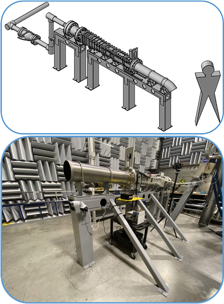
The latest addition to the gas dynamics was in 2018 with the installation of the quad-sonic wind tunnel (QSWT). The QSWT is a blow down tunnel comprising four interchangeable converging-diverging nozzles that produce Mach numbers of 2, 3, 4 and 5 through a 4-inch x 6-inch (H x W) test section. A rendering of the QSWT concept is shown in Figure 1a alongside a digital image after fabrication and installation.
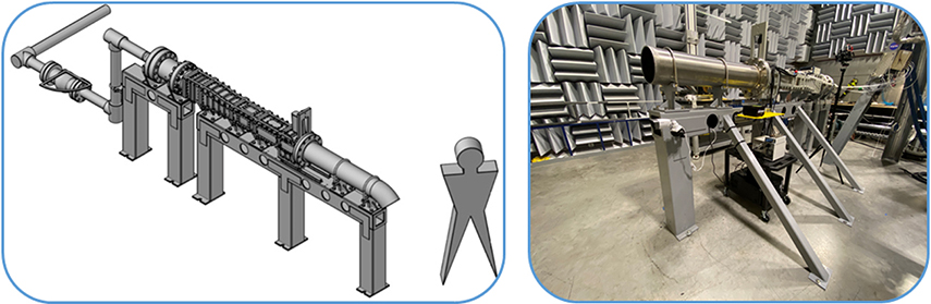
Figure 1: (a) Rendering and (b) image of the Quad-Sonic Wind Tunnel..
The floor of the QSWT has several removable inserts that provide access to the test section and for mounting different test hardware. Figure 2a shows a generic conical shaped test article during testing in QSWT. Run times are on the order of 10s of seconds, depending on the nozzle and starting tank pressure. Figure 2b illustrates a run time of 35 seconds of the Mach 5 nozzle using a starting tank pressure of 1000 psi. Given the charge rate of the compressor, several extended run times of the QSWT can be performed during a typical workday. Several static wall pressure sensing taps are placed throughout the QSWT and are monitored using a 16 channel gas pressure scanner during each run.
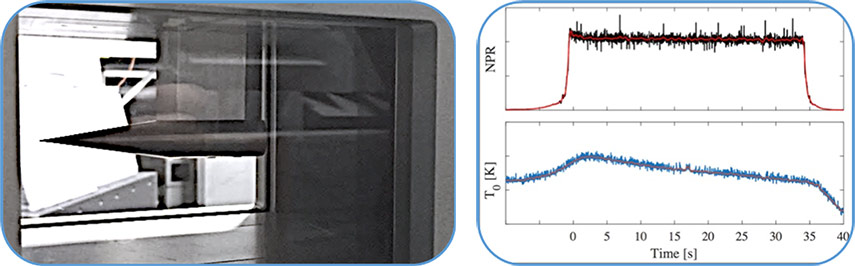
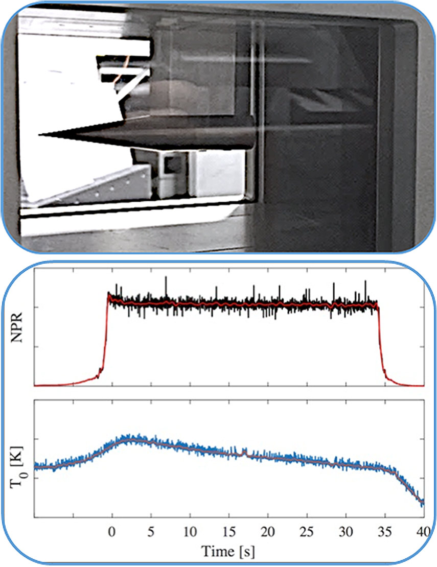
Figure 2: (a) Generic test article being studied in the test section of the QSWT. (b) Measured run time of the Mach 5 nozzle with an initial tank pressure of 1000psi.